Over the last few years, Additive manufacturing(AM) has been sculpting the manufacturing domain in revolutionary ways. Attracted by the various advantages including the countless design possibilities unlocked by AM, more and more industries are adopting AM. The early adopters of the rapidly evolving AM technologies are the aerospace industries and biomedical industries. Today, one could already fly in planes with several additively manufactured components or print themselves an implant specifically designed for their body.
One of the main focus points of AM is that, it is a smaller part of the bigger picture – INDUSTRY 4.0. AM is helping industries live up to the slogan – ‘Mass producing customized goods’. AM initially started as a rapid prototyping technology and now has found a place in day-to-day manufacturing. Unlike subtractive manufacturing where design changes are expensive, AM offers a simple way to change and improve the design with each manufactured part if necessary. All it takes is to tune the design of the virtual model of the work being manufactured. This direct link from the virtual software to physical machines makes it a valuable component of INDUSTRY 4.0.
With huge number of commercial machine manufacturers and commercial processes, the nomenclature of AM processes for metals is ambiguous. However, one can classify all the processes under a few categories 1.
Metallography for Additive Manufacturing
Contents
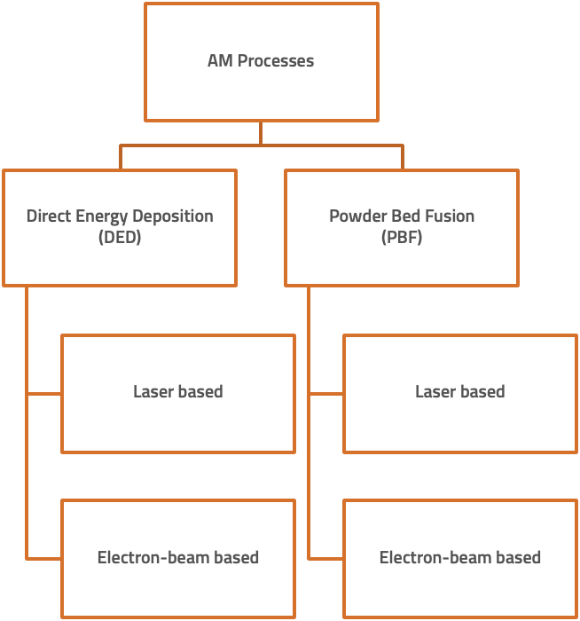
While it sounds simple, the amount of research that goes into AM to ensure the quality of a build is tremendous. While standards are designed and developed continuously, AM is extremely flexible and design-dependant with a huge number of machine parameters in play. Some of the many parameters than influence the final properties are :
- Powder chemistry.
- Powder shape and size.
- AM technology and machine model.
- Laser beam characteristics – shape and power in Laser-based processes / Electron beam characteristics in Electron based processes.
- Orientation of the build.
It is important to understand the influence of all such parameters on the microstructure of a material to explore the AM technologies to the fullest. Microstructures of additively manufactured materials can be starkly different from conventionally manufactured materials. This often results in improved mechanical properties. This page discusses with a case study on looking into the microstructure of a additively manufactured material.
1/ Metallography
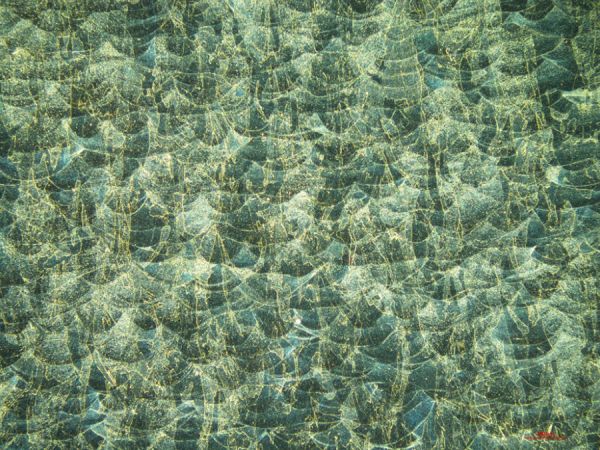
Since microstructure directly determines the mechanical properties of the final part, it is important to characterize the microstructural influence of all the machine parameters and powder characteristics. For example, the build direction can change the properties of a part because, the grains could be columnar along an axis or there could be segregation of precipitates such as carbides(in stainless steels) along the melting/sintering tracks. Hence in a lot of cases, metallurgists look into the microstructure in both longitudinal and transverse directions with respect to the build direction.
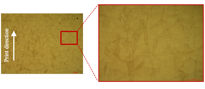
Microstructure in the printing direction showing the characteristic wavy pattern of stratified powder layers bonded together when etched with Kalling’s reagent. The Austenitic grains can be noticed to be elongated in the direction of printing.
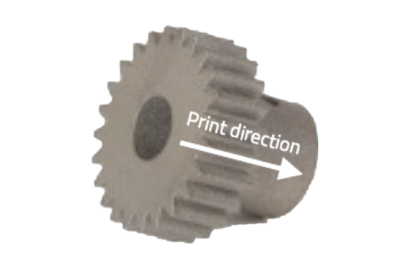
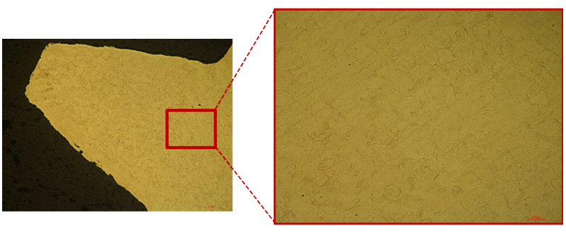
Microstructure perpendicular to the printing direction showing more equiaxed austenitic grains unlike in the printing direction. Because of such a difference in the morphology of the grains in different directions, one can expect different mechanical propertied in two directions.
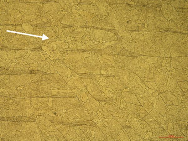
Powder fusion tracks(Fusion tracks) from laser sintering seen from slightly over etching the samples.
The recently growing field of additive manufacturing is motivating research in industries to explore aluminium alloys extensively to generate novel microstructural features that result in well-engineered like never before. An example is the same alloy A205 discussed above whose properties were improved drastically through additive manufacturing.
Be it the precipitates, or the dendrites in casting or the grains in wrought alloys, samples have to be prepared flat and free from embedded abrasives to derive accurate information from the microstructures. In most cases, the polishing process will have to be optimized for the information to be gathered. However, this page gives you the general guidelines to follow while preparing an aluminium alloy for metallography.
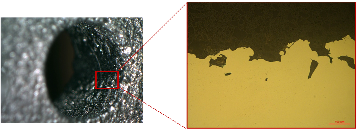
Microstructure along the walls of a hollow feature on an additively manufactured titanium Ti-6Al-4V part showing improper fusion of powders.
Such defects shown above can be eliminated by post-process surface treatments. More dangerous are the defects in the bulk of the manufactured part. Shown below is a classical defect resulting from improper fusion between powder layers. This can be due to entrapment of gases or oxide inclusions while printing.
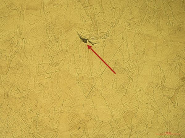
Microstructural defect (red arrow) from improper fusion of layers in additively manufactured steel 316L alloy.
2/ Sample preparation methods
In order to analyze the microstructure, the sample has to prepared without damaging the microstructure. Here below are the methods to follow during each step in the sample preparation process to properly analyze the microstructure.
- Cutting
- Mounting
- Grinding and polishing
Cutting
While preparing a metallographic sample of an additively manufactured part, the regions of interest have to be chosen carefully. Once the region is chosen, the cutting consumables, machine and holding systems can be rightly chosen. Often multiple cuts are required to separate the region of interest.
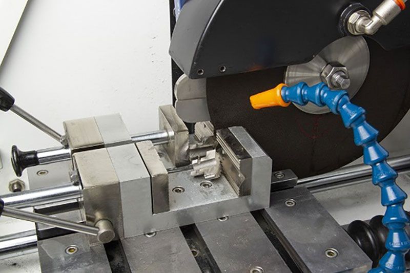
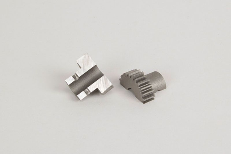
Additively manufactured piece(Steel 316L) cut using LAM PLAN Precision Red cutting wheel right though the feature of interest – hole perpendicular to the axis of the gear.
Cutting wheels
For rough cutting LAM PLAN Excellence wheels can be used. For precision cutting applications, LAM PLAN Precision cutting wheels are recommended. For more advice on cutting consumables and parameters refer to our posts on the metallography of specific material being cut.
Fixing the workpiece
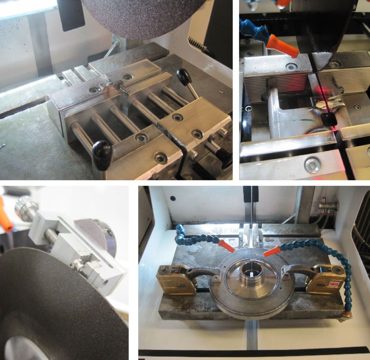
Depending on the form and size of the workpiece, a vise or a fixation system should be chosen. The complex shapes of AM parts can add complications to this process. LAM PLAN’s fixation systems avoids excessive vibrations and dangerous release of pieces from the fixation systems while cutting with Cutlam machines.
Cutting fluid
For ferrous alloys, LAM PLAN Cutting fluid 722 is recommended to be used to avoid excessive heating and microstructural deformation. The fluid provides the right proportion of lubrication and cooling effect making it ideal for metallographic applications.
For sectioning non-ferrous alloys, LAM PLAN Cutting fluid 723 is preferable.
Mounting
AM parts whenever resistant to temperatures above 180oC are hot mounted. Phenolic resins offer quick mounting solutions. However, when analysis of edges becomes critical, Epoxy resins such as 633 or 634 are great choices. Epoxy resins have a very small shrinkage, hence avoids gap between the mounted piece and the resin. This absence of gap also prevents cross-contamination of abrasives between polishing steps. Also, by avoiding the etchant to ooze out, they offer a solution for uniform etching.
When the parts cannot be heated to high temperature, for example, when made of aluminium, cold mounting is preferable. Lamplan’s widely used CMR-free 605 resins can offer quick and easy-to-use cold mounting solutions. When edge retention becomes critical, polyester-based resin 607 or CMR-free epoxy resins 603 and 603.2 works effectively.
To know more about all our mounting consumables:
Grinding and Polishing
For grinding and polishing, the same polishing procedures recommended for conventionally manufactured materials can be used. Given below are generalized polishing procedures that have worked efficiently on additively manufactured Aluminium, Titanium, and Steel alloys.
Aluminum alloys

Titanium alloys

Steels

CW – Clockwise / CCW – Counter Clockwise / Head direction: CW (the procedure is presented of polishing 6 mounted samples of diameter 30 mm)
For advice on polishing steps, refer to our posts on metallography of specific materials:
3/ Troubleshooting
Listed below are some solutions to common problems that can arise during metallographic sample preparation of steels.
-
Burning marks on cut surface
-
Cause(s)
• Feed speed too high.
• Wrong choice of cutting wheel.
• Insufficient coolant flow. -
Solution(s)
• Check if the cutting wheel is right for the material being cut.
• Reduce the feed speed.
• Focus the coolant on the cutting region. If necessary replace the coolant.
-
Scratches persist on Microstructure after final polishing
-
Cause(s)
• Contamination of polishing pad.
• Improperly cleaned samples after pre-polishing.
• Gap between mount and the sample. -
Solution(s)
• Replace the polishing pad. Store the polishing pad in a closed cupboard/BoxLam.
• Rinse the samples well after each polishing step. Use Ultrasonic cleaner before final polishing.
• Try Epoxy resins to avoid gap around the specimen.
-
Non-uniform etching of the sample
-
Cause(s)
• Wrong etchant/etching technique.
-
Solution(s)
• Choose the right etchant and technique for your alloy (Ref.: ASM Handbook).
-
Embedded abrasives after polishing
-
Cause(s)
• Excessive usage of abrasive slurries.
• Excessive force while polishing. -
Solution(s)
• Reduce abrasive dosing frequency.
• Reduce polishing force.
-
Smeared layer on the surface
-
Cause(s)
• Improper drying after polishing.
-
Solution(s)
• Use alcohol to clean the surface.
• Blow dry the surface thoroughly after cleaning.
• Use LAM15 for wiping the surface.
-
Excessive relief around porosities and defects
-
Cause(s)
• Long polishing times on a napped cloth.
-
Solution(s)
• Reduce polishing time with colloidal silica.