Aluminium alloys offer light-weight solutions for structural applications making them widely used in the Aerospace and Automotive industry. Their high specific strength positions them advantageously in the material selection charts. Another valuable quality they possess is their recyclability. For many aircraft components, this makes them strong competitors against polymer matrix composites. However, their principal disadvantage is that they lose their strength drastically at higher temperatures.
Hundreds of aluminium alloys exist in the market and their microstructures have been thoroughly studied making metallography a valuable tool to characterize and control the quality of aluminium alloys. However, the ability of the alloy to be deformed easily pose challenges in metallographic sample preparation. Irrespective of the aluminium alloy you analyze, this page will equip you with the necessary knowledge to prepare metallographic samples easily without errors.
Metallography of Aluminium
Contents
1/ Metallography
Aluminium alloys can be cast or wrought or additively manufactured. Depending on the manufacturing method and chemical composition, the information of interest gathered through metallography can vary greatly. For example, in cast Al-Si 6-series alloys, industries would be most interested in the size and morphology of eutectic precipitates. On the other hand, cast alloys such as A205 show completely unconventional microstructures which necessitates studying a lot more than just precipitates. In foundries and metal-bonding/welding industries, metallography is used as a simple tool to look into micro-defects such as porosities and inclusions. A broad overview of the features analyzed by industries working on Aluminium alloys through metallography are shown below:
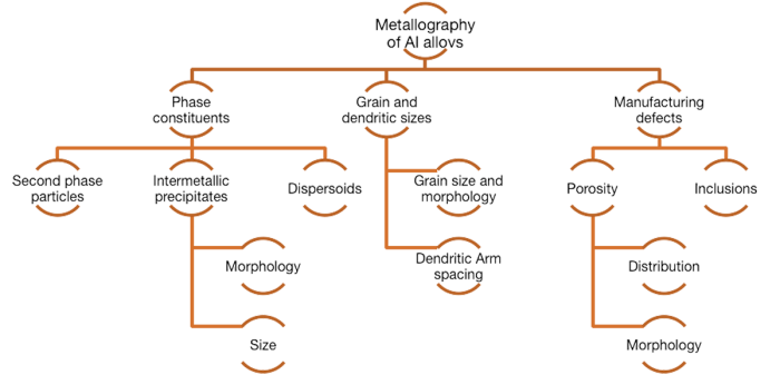
Some of the many features analyzed in aluminium alloys through metallography are discussed below.
Phase constituents
Aluminium-Copper alloys
Aluminium alloys are extensively alloyed with a variety of alloying elements. Depending on the alloying elements present, intermetallic precipitates are formed which positively or negatively affects the properties of the manufactured part. Such precipitates play a critical role in post-treatment processes such as age-hardening. The capacity of an aluminium alloy to age harden is known from its composition and its phase-diagrams. In age-hardening alloys, such as Al-Cu alloys for example, the sizes and morphology of one such precipitate between aluminium and copper are tailored through heat treatment processes to have the desired mechanical properties. Sometimes, these strengthening precipitates can be very small to be characterized by a light microscope and need an electron microscope to be imaged.
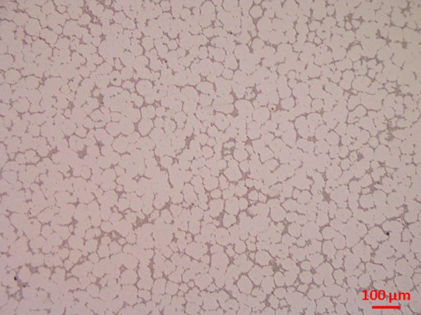
Microstructure of a cast novel Al-Cu-TiB2 alloy A205 showing a spheroidized cast structure with TiB2 particles at the boundaries.
This unconventional structure makes it one of the strongest cast alloys in the market. Owing to the presence of copper, these alloys can the age-hardened.
Aluminium-Titanium alloys
In some cases, as in Al-Ti alloys for example, there can be very hard precipitates such as TiB2 or Al3Ti that help with grain refinement(in turn strengthening the alloy). Such precipitates can be imaged and their morphology can be studied right after final polishing without any etching. One has to be careful while judging the nature of a precipitate form a microstructure. For example, to precisely say the precipitate is an Al3Ti intermetallic, tools such as EDS (Energy Dispersive Spectroscopy) are necessary. Once the alloy has been thoroughly studied, optical microstructures can be quickly used for quality control and morphological studies on precipitates.
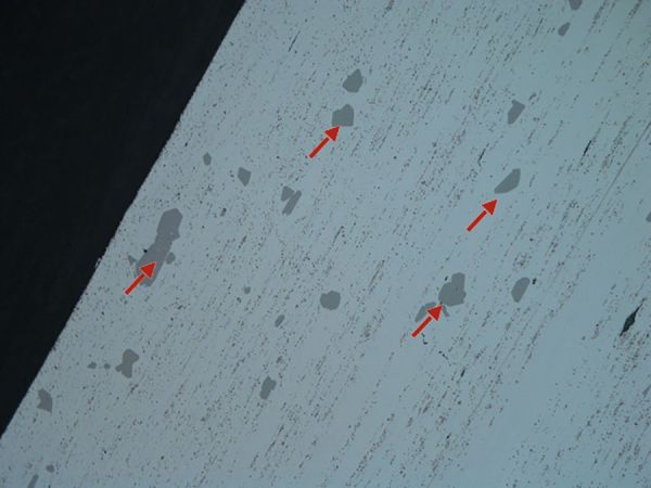
Microstructure of an Al-Ti alloy magnified to 200x showing islands of Al3Ti precipitates(red arrows) in the aluminium matrix.
The particles can be distinguished clearly right after polishing with colloidal silica.
Aluminium-Silicon alloys
Al-Si alloys are characterized by a eutectic phase system(eutectic composition ~12.6wt% Si). A typical hypo-eutectic Al-Si alloy would have the eutectics microstructurally distributed in between the aluminum dendrites whereas an hyper-eutectic composition would have the eutectics spread throughout with primary silicon particles embedded in the eutectic matrix.
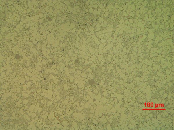
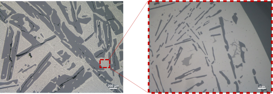
The intermetallics formed in the widely studied and used Al-Si alloys can be more complex as multiple elements can be present in the alloy. In Al-Si alloys containing Fe and Mg, a very known morphology of the precipitates is the ‘chinese script’. It is interesting to note that the composition of the precipitate not only change the morphology but also the color they take under a light microscope after polishing with colloidal silica.
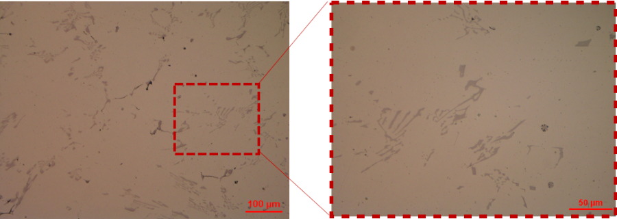
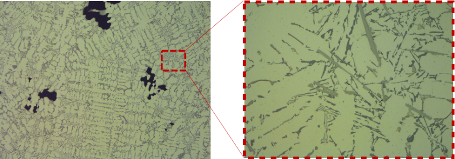
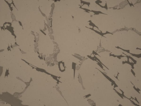
The exact composition is to be confirmed by EDS analysis or selective etching techniques.

Manufacturing defects
Defects, like in many non-ferrous alloys, are ubiquitous in aluminium alloys. In cast aluminium alloys, the specimens are critically controlled for porosities as they can be very detrimental to the mechanical properties of the alloy. There are two main types of porosities that occur in aluminium alloys – 1. Gas porosities and 2. Shrinkage porosities. While gas porosities are usually spherical in shape, shrinkage porosities are irregular and very pronounced in cast parts. While gas porosities are kept in check by controlling the casting atmosphere or by post-casting processes such as Hot Isostatic Pressing, the shrinkage porosities are best controlled by optimizing the casting parameters.

For several applications, aluminium alloys are welded or brazed. The temperature gradients created from the joining processes in aluminium alloys add complications as the alloys are very susceptible to damage from uncontrolled local heating. For example, the microstructure below of a welded aluminium alloy suggests intergranular fusion voids possibly caused by eutectic melting as a result of temperatures exceeding solidus temperatures (where micro-constituents of the alloy begin melting).
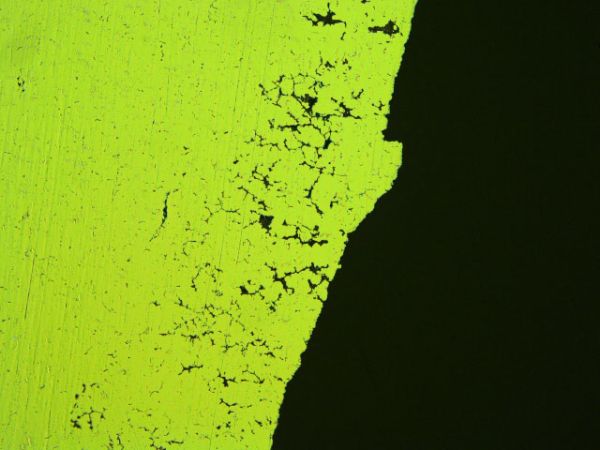
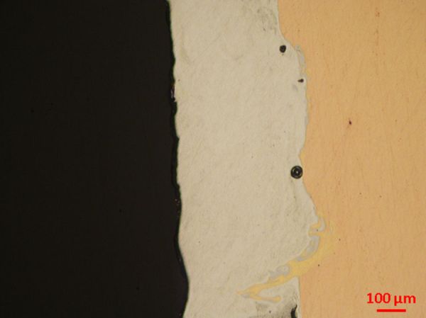
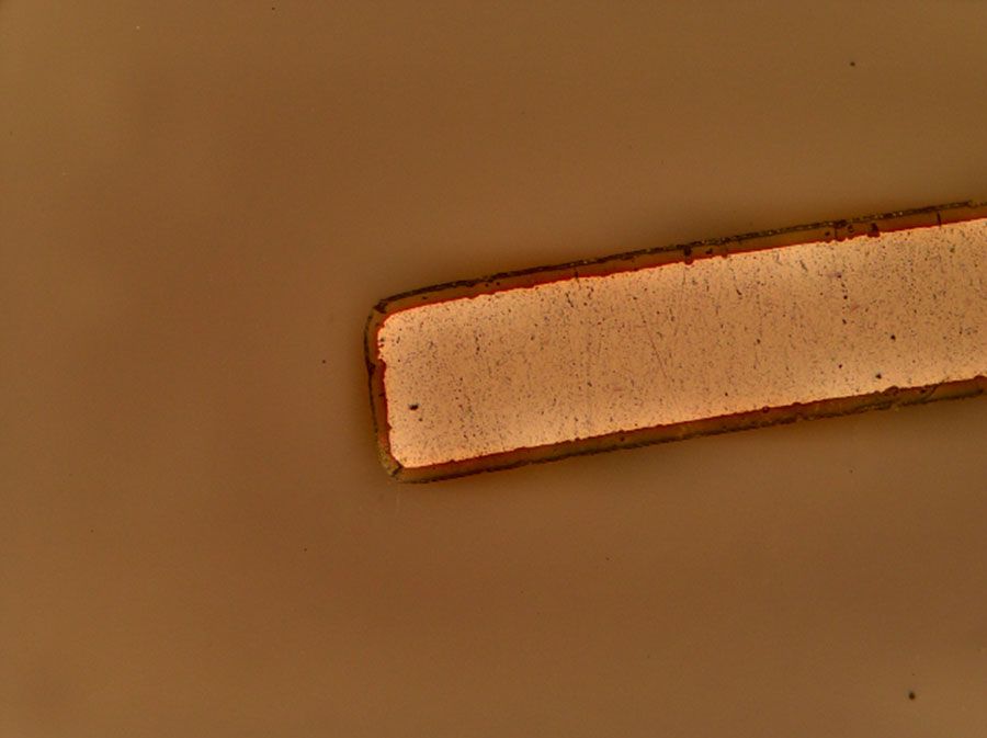
Microdefects revealed in copper-aluminum bonded layers after polishing on Touchlam 2TS3 with Biodiamant Neodia 3P.
It should be noted that, metallography is as much as a quantitative technique as it is a qualitative technique in several industries. More and more companies opt for digitized and automatic measurement processes for characteristics such as grain size measurement, precipitate morphology, porosity fraction, and dendritic spacing. Automation of the metallographic analysis, especially in production industries offer repeatability and reliable precision in the analysis.
As an example, an automatic porosity fraction measurement model in a cast Al-Si alloy on a software such as Image would work the following way:

The process can be repeated over wp-content/uploads from different locations on the sample to statistically measure the distribution of porosities automatically.
The recently growing field of additive manufacturing is motivating research in industries to explore aluminium alloys extensively to generate novel microstructural features that result in well-engineered like never before. An example is the same alloy A205 discussed above whose properties were improved drastically through additive manufacturing. Also additive manufacturing comes with a variety of new quantitatively informative features than can be measured from microstructures – such as the layer overlapping or penetration depth, and bead sizes.
Be it the precipitates, or the dendrites in casting or the grains in wrought alloys, samples have to be prepared flat and free from embedded abrasives to derive accurate information from the microstructures. In most cases, the polishing process will have to be optimized for the information to be gathered. However, this page gives you the general guidelines to follow while preparing an aluminium alloy for metallography.
2/ Sample preparation methods
In order to analyze the microstructure precisely, the sample has to prepared without damaging the microstructure. Damage to the microstructure can arise from 3 principal causes:
- Deformation from cutting and grinding which can extent to greater depths in softer aluminium alloys because of their ductile nature
- Embedding of abrasive particles in the metal during polishing
- Relief between the matrix and hard second phase particles that can be present in the alloy.
Shown below compares a surface polished improperly and the same surface polished rightly with the proposed polishing method.
- Cutting
- Mounting
- Grinding and polishing
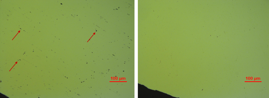
Surface of a polished aluminum alloy (on the left) with embedded abrasives from bad sample preparation methods and (on the right)with minimized damage from embedded abrasives.
Here below are the methods to follow during each step in the sample preparation process to properly analyze the microstructure.
Cutting
Aluminium alloys are soft and ductile relative to other commonly used metals. This makes them susceptible to extensive microstructural damage if no care is taken while cutting. This section provides the necessary cutting consumables and methods to avoid microstructural damage.
Cutting wheels
For cutting aluminium alloys, SiC-based grinding wheels are recommended. Lamplan Excellence H4 wheels can be used for coarse cutting or Lamplan Precision Blanc wheels for fine cutting. Using precision wheels result in finer scratches making the polishing process shorter.
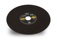
| Excellence H4 | Coarse cutting all aluminium alloys |
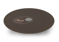
| Blanc | Precision cutting all aluminium alloys |
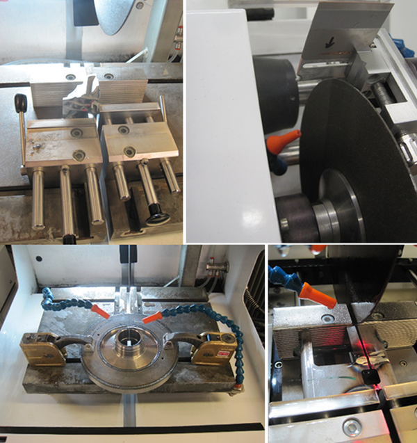
Fixing the workpiece
Depending on the form and size of the workpiece, a vise or a fixation system should be chosen. Lamplan’s fixation systems avoids excessive vibrations and dangerous release of pieces from the fixation systems while cutting with Cutlam machines.
Machine parameters
Among the various parameters, the rotational speed of the wheel and feed speed are the most important.
The chart below presents the optimal rotational speed based on the diameter of the cutting wheel.
When there are fragile phases or brittle coatings in the workpiece to be cut, the precision cutting wheels have to be used with a feed rate less than 0.3 mm/s to avoid damage. For coarse cutting aluminum alloys, Excellence H4 wheels can be used at feed speeds up to 1 mm/s.

Cutting fluid
Lamplan Cutting fluid 723 is recommended to be used to avoid excessive heating and microstructural deformation. The fluid provides the right proportion of lubrication and cooling effect making it ideal for metallographic applications.
Mounting
Mounting the specimens allow easier handling of the material while polishing. Mounting is necessary for using semi-/auto-matic polishing machines.
Aluminium alloys can be sensitive to temperatures above 150oC which is generally attained in hot mounting processes. Hence cold mounting is usually preferred for aluminium alloys.
Lamplan’s widely used CMR-free 605 resins can offer quick and easy-to-use cold mounting solutions. When edge retention becomes critical, polyester-based resin 607 or CMR-free epoxy resins 603 and 603.2 works effectively.
When the specimen is being prepared for SEM-analysis, a conductive resin is recommended.
To know more about all our mounting consumables, visit:
Grinding and Polishing
According to the ASM Handbook for Metallography, the objectives of a properly polished specimen are:
- No deformation from cutting
- No scratches from grinding and polishing
- No pullouts of the brittle structure constituents
- No introduction of foreign particles
- Flat and retained edges
- No thermal modification of the microstructure
Keeping that in account, Lam Plan proposes the following method for hassle-free metallography of general aluminium alloys.
The first step is usually coarse grinding to render the samples flat. SiC papers are widely used for grinding aluminium alloys as they offer fast material removal. It should be made sure that, the layers of deformation from cutting have to be removed.
Once the samples are flat, they can be pre-polished/polished. Lamplan Touchlam 2TS3 are very effective when used with Neodia abrasives on aluminium alloys. The pad also maintains the samples flat during the polishing process.
Often, this polishing step is supplemented by a finer polishing step to refine the scratches further to analyse the microstructure are higher magnifications (>200X) or even an SEM (Scanning Electron Microscope). This step can be definitely skipped when only relatively large features are being analysed.

CW – Clockwise / CCW – Counter Clockwise / Head direction: CW for all steps
(the procedure is presented of polishing 6 mounted samples of diameter 30 mm)
As discussed under the section – Metallography, many analyses on aluminium does not demand etching. However, etching can help greatly to enhance contrast in the feature to be studied. When samples are prepared for grain size analysis, etching helps reveal the grain boundaries. In some cases, one can also use different illumination techniques such as the polarized light to enhance contrast between micro-constituents with or without etching. Depending on the alloy and the feature to be studied, consulting the ASM Handbook is strongly recommended. As a general rule of thumb, many industries use Keller’s reagent as it is relatively easy to prepare and use. Extreme caution has to be taken with its usage as it includes hydrofluoric acid.
3/ Troubleshooting
Listed below are some solutions to common problems that can arise during metallographic sample preparation
of aluminium.
-
Scratches persist on microstructure after final polishing
-
Cause(s)
• Contamination of polishing pad
• Improperly cleaned samples after pre-polishing
• Gap between mount and the sample -
Solution(s)
• Replace the polishing pad. Store the polishing pad in a closed cupboard/BoxLam
• Rinse the samples well after each polishing step. Use Ultrasonic cleaner before final polishing
• Try Epoxy resins to avoid gap around the specimen
-
Non-uniform etching of the sample
-
Cause(s)
• Wrong etchant/etching technique
-
Solution(s)
• Choose the right etchant and technique for your alloy (Ref.: ASM Handbook)
-
Embedded abrasives after polishing
-
Cause(s)
• Excessive usage of abrasive slurries
• Excessive force while polishing -
Solution(s)
• Reduce abrasive dosing frequency
• Reduce polishing force
-
Smeared layer on the surface
-
Cause(s)
• Improper cleaning and drying
-
Solution(s)
• Use alcohol to clean the surface
• When colloidal silica is used, flush water on the pad during last 30 seconds of polishing
• Blow dry the surface thoroughly after cleaning
• Use LAM15 for wiping the surface
-
Excessive relief around porosities
-
Cause(s)
• Long polishing times on a napped cloth
-
Solution(s)
• Reduce polishing time with colloidal silica
