Sectioning, or cutting, involves extracting a piece of a sample with the cross-section of interest to be polished and imaged under a microscope.
For metallography, dedicated machines are available in the market to perform such cutting operations under conditions that would mitigate the deformation the material is subjected to.
Choosing the right sectioning technology for your metallographic sample preparation
Contents
Cutting for metallography
While there are many coarse cutting methods such as hack-sawing, wire cutting, or dry abrasive cutting, these techniques induce an unhealthy amount of deformation for microstructural analyses either from mechanical or thermal stresses. Metallographic cutting machines, on the other hand, avoid such detrimental effects through the use of abrasives in the form of resin(/rubber)-bonded cutting wheels combined with the use of cutting fluid.
Metallographic cutting works primarily by driving an abrasive wheel, rotating at speeds around 3000 rpm, into a material to be cut while the area of cut is flooded with a coolant/lubricant. At such high speeds, the cutting wheel is engineered to optimally wear so that new abrasives get continuously revealed during the process of cutting replacing older abrasives that lose their cutting capacity. While it is impossible to eliminate the microstructural damage completely, through the continuous action of wear and tear, the cutting wheel cuts through the material with a minimized amount of microstructural damage. While the choice of consumables, hence, is a material-sensitive subject, this post focuses on the mechanical aspects of a metallographic cutting machine.
What’s in a metallographic cutting machine?
A metallographic cutting machine has three principal parts:
- A motor with a cutting wheel
- A table combined with vises to hold the sample
- A tank with a pump that holds and recirculates cutting fluid
Developments in various aspects of the machine enable us to cut parts with increasing levels of complexity. For example, with Additive manufacturing, industries are exploring the best topography optimizations which in many cases increase the complexity of a part. Such complex parts cannot be cut by a simple Z-cut and one may need special vises.
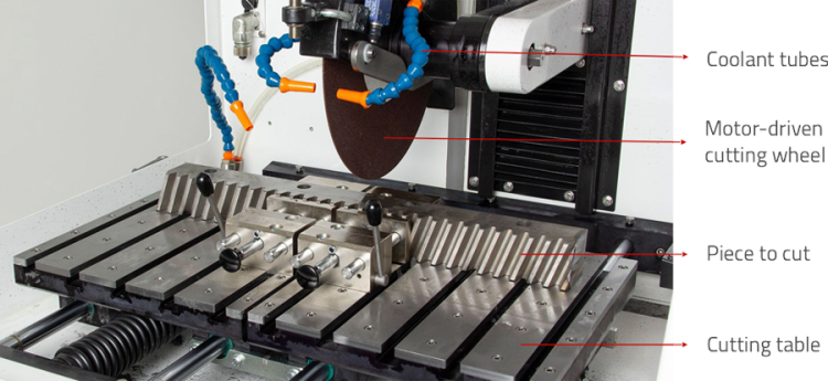
Constituents inside a metallographic cutting machine (CUTLAM 3.1) where the table moves front and back while the cutting wheel moves up and down.
Cutting Motor
To drive the cutting wheel through the material and for the abrasives to develop a cutting action, enough torque has to be developed by the motor. When the cross-section of the material is huge or when the material is hard, more torque is to be generated by the motor. In simpler terms, the bigger and harder the sample is, the more is the resistance to cut and hence the need to have a better-powered motor. The need to have a powerful motor is counter-balanced by the choice of cutting wheel, cutting plans, and cutting techniques. When the cutting wheel is efficient, cutting action can be induced at lower torque levels.
The power of a cutting motor increases roughly with the size of the machine, which marks a corresponding increase in the size of samples that can be cut.
While in some machines, the motor is placed within the cutting chamber, in most cases, it is concealed behind the machine and the cutting wheel is belt-driven.
Cutting Table
The cutting table is the platform where the sample is tightened using a vise. Two aspects characterize a cutting table: the size and the number of slots. The bigger the cutting table, the bigger the samples that can be fixed. The more the slots, the better is the flexibility to adapt the positions of vises.
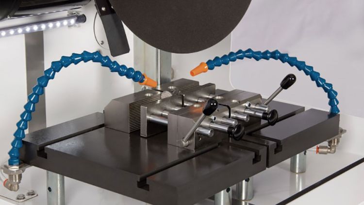
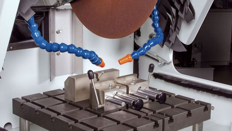
Cutting tables – (a) Smaller cutting table with fewer slots. (b) Bigger cutting table with a lot more slots for vises.
Depending on the shape of the sample and the flexibility of the cutting table, a wide variety of fixation systems are available. To add to it, supplementary cutting platforms can be added, for example, the X-table accessory to perform X-cut discussed later in the article.
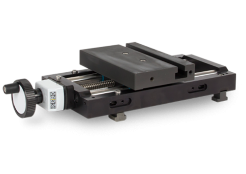
A supplementary X-table to complement the available cutting table
Fixation system
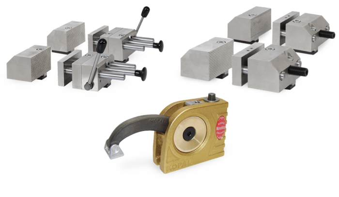
Some frequently used fixation systems – Fast tightening vises, screw vises, and Kopal system.
For metallography, sometimes, there is a special need to extract sections from peculiar and complex areas. New fixation systems can be imagined and developed for such applications. For example, it is very difficult and dangerous to clamp spherical pieces with conventional fixation systems. For such applications, unconventional fixation systems can be imagined by our technical department, as shown below.
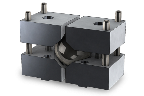
Schematic – Example of a fixation system to clamp spherical samples.
Coolant recirculation system
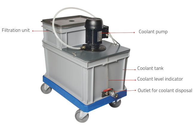
Components of a coolant recirculation system.
Cutting Techniques
X+Z/Y cut
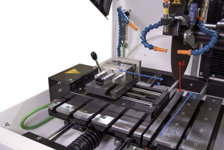
Degrees of freedom of the table and wheel in a typical metallographic cutting machine – X, Y, and Z axes. The table movement is generally limited to X and Y axes (Blue arrows) and the cutting wheel generally moves on the Z-axis (red arrow).
Z-Cut
Z-Cutting is probably the most widely used cutting technique. Most manual cutting machines use Z-cut as it is very simple to perform. Z-cutting works best when the sample does not have a complex shape.
Click here to watch a video of Z-cut in action.
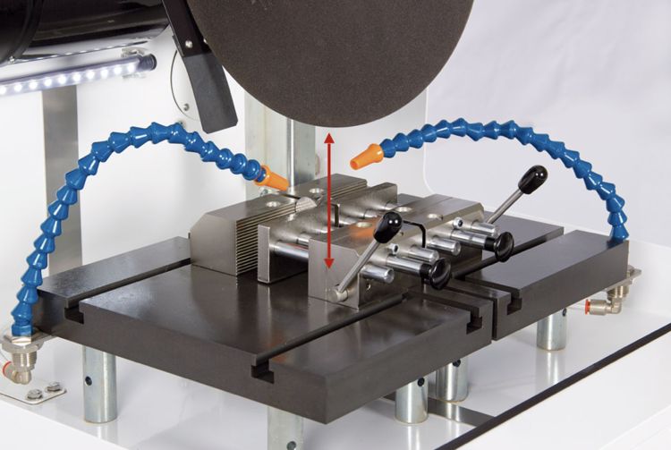
A sample cut using Z-cut. The red arrow presents the cutting wheel motion.
Y-Cut
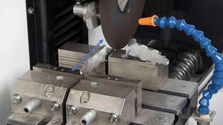
A sample cut using Y-cut. The blue arrow presents the cutting table motion.
Y+Z cut
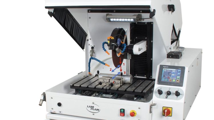
Y+Z cut performed on a cylindrical bar by moving the wheel and table alternatively as sequenced in the picture from 1 to 4.
X+Z/Y cut
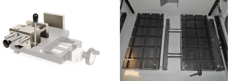
X-table options to manipulate the motion of clamped samples perpendicular to the wheel to perform serial cutting operations.
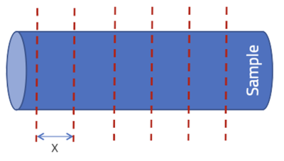
Schematic example of a serial slicing operation on a cylinder to extract slices of thickness x. This cut is easily performed with precision using an X-table.
By using an X-table as a machine feature or an accessory, precise serial cuts can be programmed. By programming the X-table to move after each cut and programming the wheel to move appropriately, slices of a sample can be extracted with ease.
Click to watch a video on using such a slicing operation on a huge automotive component.
Gravity cut
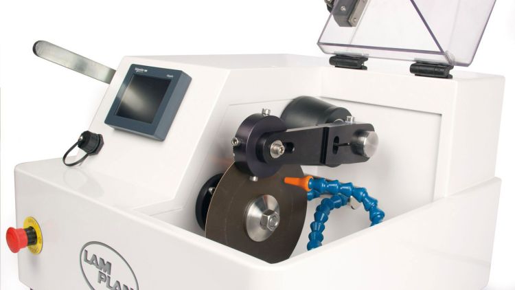
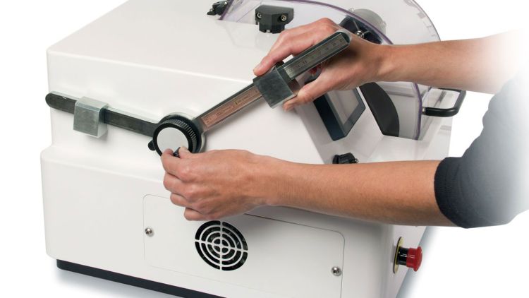
Gravity cut mechanism on a cutting machine allowing the cutting operation to be carried out with minimal force. The sliding blocks are used to manipulate the downward force applied on the sample. The knob is used to manipulate the position of the sample in the X-direction.

Schematic example of a serial slicing operation on a cylinder to extract slices of thickness x. This cut is easily performed with precision using an X-table.
The gravity-fed cutting technique uses a minimum cutting force, hence induces the minimum amount of deformation in the piece. The cons of the gravity feed cutting technique are that it is slow and cannot be used for cutting big samples. It is usually adapted in small cutting machines where precision is the most desired aspect of cutting.
Conclusion
This article discussed the components of a metallographic cutting machine and different cutting techniques than can be used based on the objective by taking advantage of the mechanical features of the machine. The possibilities are not limited to the presented techniques. For example, operation-specific mechanics can be imagined for slicing operations (see picture below).
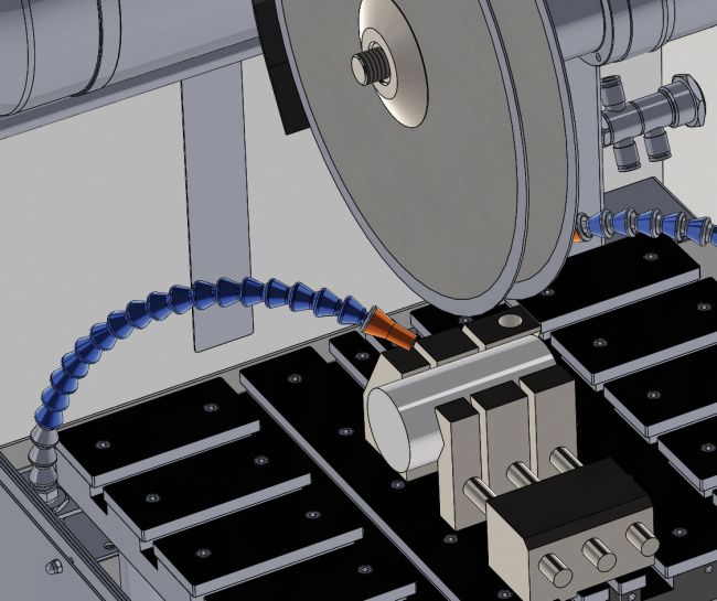
Schematic of a double disk cutting machine for quick parallel slicing operations doubling productivity.
Get in touch with our technical team (essais@lamplan.fr) to discuss possible improvements at your metallographic lab. For material-specific advice, check out our other posts on Box of Knowledge here.