Composites bring the advantages of two different material domains together. A material forms the matrix and another material forms the reinforcing phase, combinedly resulting in a composite. Depending on the matrix material, composites can be classified as Polymer Matrix Composites (PMCs), Metal Matrix Composites (MMCs), and Ceramic Matrix Composites (CMCs). The reinforcing phases are generally harder and stronger than the matrix. Also, the reinforcing phases can be continuous – such as laminates or fiber, or discontinuous – such as whiskers or particles. This page focusses on metallography of fiber reinforced polymer matrix composites.
Fiber reinforced polymer matrix composites have found wide applications in aircraft and automotive industries. The main advantage is their directionally engineerable mechanical strength and toughness. By controlling the orientation of the fibers and their proportion in the matrix, their mechanical properties can be controlled. Conventionally glass fibers were widely used as a reinforcing phase. Recently, carbon fiber reinforced composites have become very popular because of their enhanced mechanical properties.
Metallography of Fiber reinforced composites
Contents
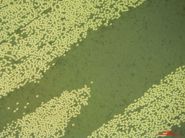
Microstructure of a unidirectional carbon fiber reinforced composite perpendicular
to the fiber orientation after a 4-step polishing procedure (Scale bar is 100 µm).
1/ Metallography
The main aspects of interest in microstructural analysis fiber reinforced composites are:
1. Fiber distribution in the matrix
2. Morphology of fibers
3. Defects in the composite
Defects are very common in polymer matrix composites and can be very detrimental to the mechanical strength of the composite. When polishing parallel to the fiber orientation, special care has to be taken to avoid fibers pulling out during polishing.
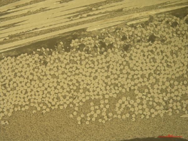
Microstructure of bidirectional glass fibre-reinforced composite suggesting defects in the fibres
and porosities from manufacturing (Polished using procedure given in the post).
2/ Sample preparation methods
- Cutting
- Mounting
- Grinding and polishing
Cutting
Cutting wheels
For cutting fiber reinforced composites, Diamond based cutting wheels are recommended. The thin LAM PLAN Precision Black cutting wheels offer a precise cut while minimizing damage to the composite microstructure. The abrasives on Diamond wheels can lose sharpness after cutting for extensive periods of time. A dressing stone should be used to restore cutting efficiency.
Fixing the workpiece
Depending on the form and size of the workpiece, a vise or a fixation system should be chosen. Lamplan’s fixation systems avoids excessive vibrations and dangerous release of pieces from the fixation systems while cutting with Cutlam machines.
Machine parameters
Among the various parameters, the rotational speed of the wheel and feed speed are the most important. The chart below presents the optimal rotational speed based on the diameter of the cutting wheel.
To have minimum damage, slow cutting speeds such as 0.3 mm/s are recommended for cutting PMCs. Individual fiber strands can generally be cut using scissors.

Cutting fluid
Lamplan Cutting fluid 722 can be used for metallographic sectioning of PMCs.
Mounting
Since PMCs are sensitive to high temperatures, they are cold-mounted. The important criteria for mounting free fibers or composites is the shrinkage. Resin shrinkage can cause a gap between the specimen and the mount which can result in damaged microstructure. The composite has to be held rigidly in the mount to avoid damage. For this purpose, Resine 607 offer quick mounting solutions. However, CMR-free epoxies can also be useful solutions.
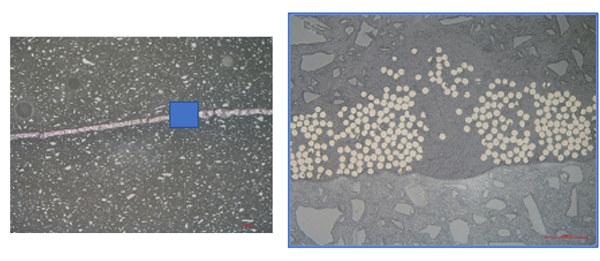
Microstructure of a layer of resin bonded carbon fibres used for manufacturing composite parts mounted in Resin 607.
To know more about all our mounting consumables visit:
Grinding and Polishing
The first step is usually coarse grinding to render the samples flat. SiC papers are widely used for grinding PMCs as they offer fast material removal.
Once the samples are flat, they can be pre-polished/polished. Lamplan Touchlam 2TS3 are very effective when used with Neodia abrasives on PMCs. The pad also maintains the samples flat during the polishing process.
For grinding and polishing PMCs, central pressure is preferred to individual pressure. The central pressure system help maintain the samples flat and avoids fiber pull-outs especially when polishing is carried out parallel to the fibers’ orientation. The picture below shows the result of a case-study that compares the result from using individual against central pressure for polishing. The aim was to analyze the defects from manufacturing. Fiber-pullouts that occur during grinding and polishing mask other defects from being seen distinctly.
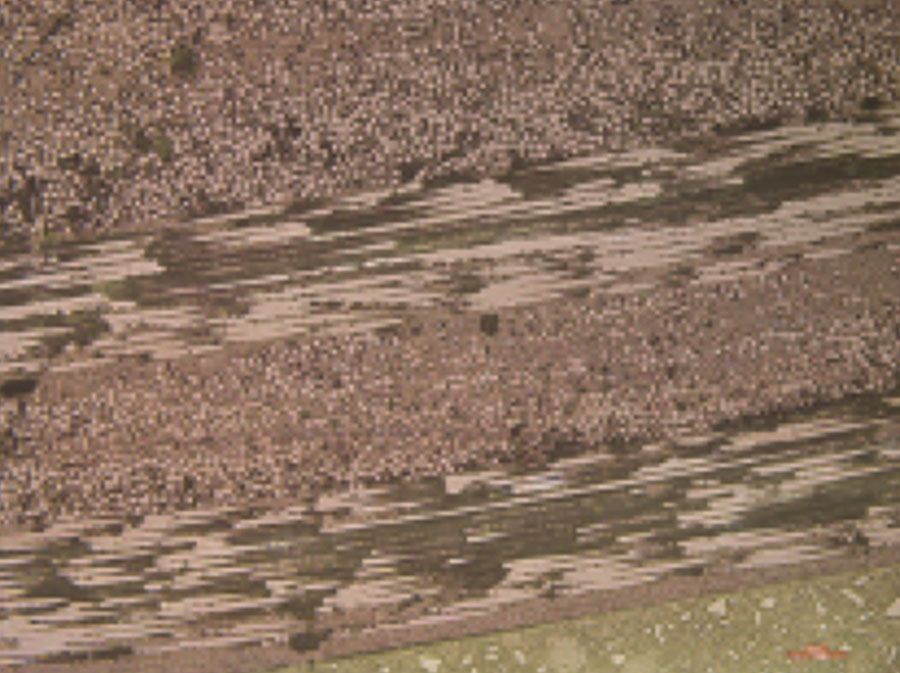
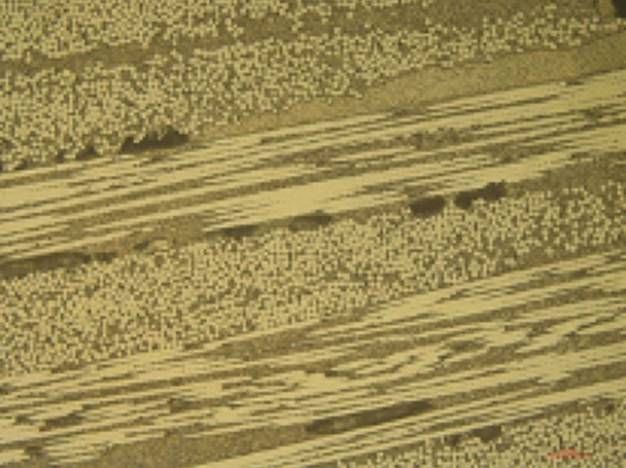
Glass-fiber reinforced PMC – polished by individual pressure showing fiber-pullouts from polishing(left); polished by central pressure with no fiber-pullouts from polishing(right)

(The procedure is presented of polishing 6 mounted samples of diameter 30 mm)
3/ Troubleshooting
-
Scratches persist on microstructure after final polishing
-
Cause(s)
• Contamination of polishing pad
Improperly cleaned samples after pre-polishing
• Gap between mount and the sample -
Solution(s)
• Replace the polishing pad. Store the polishing pad in a closed cupboard/BOXLAM
• Rinse the samples well after each polishing step. Use Ultrasonic cleaner before final polishing
-
Fibers are not well-rounded
-
Cause(s)
• Uneven removal of resin and fibers because of difference in hardness
-
Solution(s)
• Replace the polishing pad. Store the polishing pad in a closed cupboard/BOXLAM
• Rinse the samples well after each polishing step. Use Ultrasonic cleaner before final polishing
-
Smeared layer on the surface
-
Cause(s)
• Improper cleaning and drying
-
Solution(s)
• Use alcohol or demineralized water to clean the surface
• Use LAM15 for wiping the surface